



MARGE is a long-period magnetotelluric (MT) survey that aims at imaging {tip content="The electrical conductivity of the lithosphere refers to the ability of the soil to conduct electricity. This property is influenced by the soil composition, as materials with high electrical conductivity such as metallic minerals and water have a greater capability to conduct electricity than less conductive materials such as solid rocks. By measuring the electrical conductivity of the soil at different depths, it is possible to obtain information about the structure and composition of the underlying lithosphere, as well as the presence of natural resources such as minerals and hydrocarbons. Knowledge of the soil's electrical conductivity can also be used to prevent damage to electrical infrastructure during extreme events such as solar storms."}the electrical conductivity structure of the Italian lithosphere{/tip} in three dimensions (3D), with the purpose of identifying and characterizing major geological structures in the crust and upper mantle. The survey results can be combined with other available datasets, including those on gravity, seismic tomography, geochemistry, and geology. The combination of these multidisciplinary datasets will advance our scientific knowledge of the analyzed region's lithospheric architecture and evolution.
The MARGE project’s ultimate goal is to use the modeling of {tip content="The conductivity structure of the Earth refers to the spatial distribution of the electrical properties of the subsurface, particularly the distribution of electrical conductivity of the ground as a function of depth. This structure can be influenced by various factors, such as the composition of the soil, the presence of water or conductive minerals, temperature, and pressure. Knowledge of the conductivity structure of the Earth is important for many applications, such as locating natural resources such as mineral or oil deposits, better understanding geological phenomena such as earthquakes or volcanic eruptions, assessing the geothermal potential for electricity production, and modeling electromagnetic fields generated by telluric currents."}solid-Earth conductivity structure{/tip} and {tip content="The structure of impedance of the Earth's surface refers to the spatial distribution of the electrical properties of the soil in proximity of the Earth's surface. In particular, it refers to the distribution of the electrical resistivity of the soil as a function of depth. This can change significantly depending on the characteristics of the subsurface. For example, the presence of highly conductive or resistive rocks or minerals can influence the spatial distribution of impedance. Additionally, the presence of groundwater, which is a good conductor, can increase the impedance of the soil, while the presence of gas or voids can decrease it. Temperature and pressure can also affect the impedance structure. Changes in the impedance structure can be caused by natural phenomena such as sedimentation, erosion, volcanic or seismic activity, or by human activities such as building construction or soil drilling for the extraction of natural resources."}surface impedance{/tip} in order to map the magnetic-storm-induced geoelectric fields. Indeed, for the purpose of geoelectric-hazard analysis, the combination of impedance tensors and geomagnetic time series from ground-based observatories or models can be used to estimate geoelectric field variation. This will allow the development of capabilities for both real-time and historical mapping of the geoelectric field over Italy as a result of geomagnetic field disturbance. MT impedance that relates geoelectric fields to geomagnetic fields at the Earth’s surface provides a critical missing piece to estimate {tip content="Geomagnetically induced currents (GIC) are electric currents generated within the earth as a result of changes in the magnetic field. GICs can move through natural conductors in the ground, such as minerals found in rocks, or along metal pipes used to distribute electricity. When GICs pass through metal conduits in a power grid, they can cause damage to transformers and other grid components, resulting in malfunctions and, in some cases, outages. Knowing how GICs are distributed in the subsurface allows us to identify the areas most vulnerable to their influence and develop GIC prediction models."}geomagnetically induced currents{/tip}.
It is nothing but a stroke of luck that the MT impedances obtained from MT survey and modeling are exactly the type of data product necessary for {tip content="Space weather is a branch of science that studies the behavior of the Sun, the space environment, and the interactions between the Sun, Earth, and the surrounding environment. In particular, it focuses on the analysis of solar phenomena such as solar storms and coronal mass ejections, which can cause variations in the geomagnetic field and in the Earth's ionosphere. Such phenomena can have a significant impact on terrestrial technological infrastructure, such as communication systems, satellites, GPS, and power grids. Therefore, the goal of space weather is to predict and mitigate the negative effects of these phenomena on technological infrastructure and human life."}space weather hazard{/tip} mitigation. This is also why the necessity for nationwide MT impedance coverage is becoming more urgent. Nowadays such data serve the electric power grid industry as well as the solid-Earth geophysical community.
Magnetotelluric method
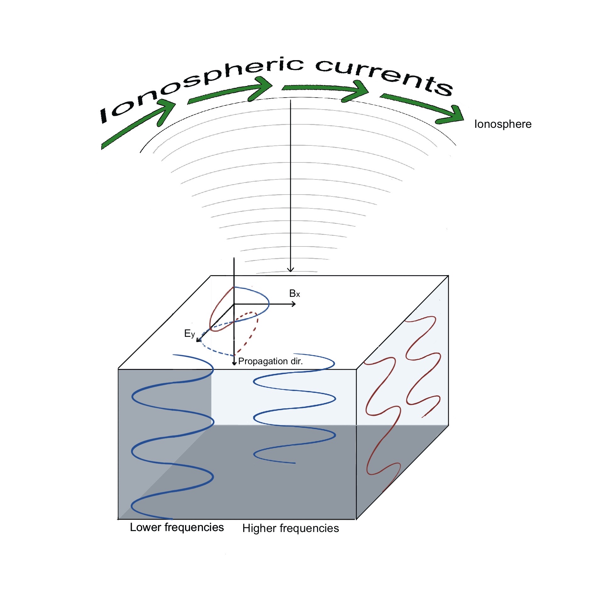
Magnetotelluric (MT) is a passive geophysical technique that can be used to assess the distribution of electrical resistivity in the Earth’s subsurface by examining the variations in the geomagnetic and electric fields that occur naturally. Different types of MT instruments, such as audio, broadband, and long-period, collect data at different frequencies, resulting in an overall investigation depth ranging from tens of meters to hundreds of kilometers.
MT source fields are produced by global thunderstorm activity as well as currents systems flowing in the magnetosphere and ionosphere due to the interactions between the solar wind and the geomagnetic field. These sources provide a broad spectrum of magnetic-field variations in the frequency range from 10-5 to 104 Hz, making them ideal for crust and upper mantle research. The strength of these signals changes over hours, days, weeks, and during the solar cycle.
The time-series measurements of the magnetic and electric fields are analyzed in the frequency domain, with lower-frequency signals corresponding to greater depth of penetration into the Earth’s subsurface. As a result, in order to image the deep crust and upper mantle, very low frequencies must be measured to achieve sensitivity to the lithosphere's base. High performance computers equipped with mathematical inversion algorithms can create a 3D Earth electrical conductivity model using these data.
MARGE data acquisition
A MARGE survey collects MT data using portable instruments on a grid of approximately 55 km. Because it is desirable to have data from both very short and extremely long periods, two different magnetic sensors are combined at each site: induction coils and fluxgate magnetometers.
Thus, in a typical MARGE MT survey station the following equipment is deployed:
- A three-component fluxgate magnetometer and dipoles with electrodes to record continuous magnetic and electric signals in the field. To ensure the MT measurement capture sufficient natural signals at longer periods, data are collected for 4-6 weeks at each site;
- Specific induction coil magnetic field sensors for broadband MT station and dipoles with electrodes to record continuous magnetic and electric signals in the field. Data are collected over the course of one week utilizing the broadband MT station.;
- Acquisition boxes containing data recording units, GPS and 12 volt battery;
- A small solar panel mounted close to the acquisition box to charge the battery.
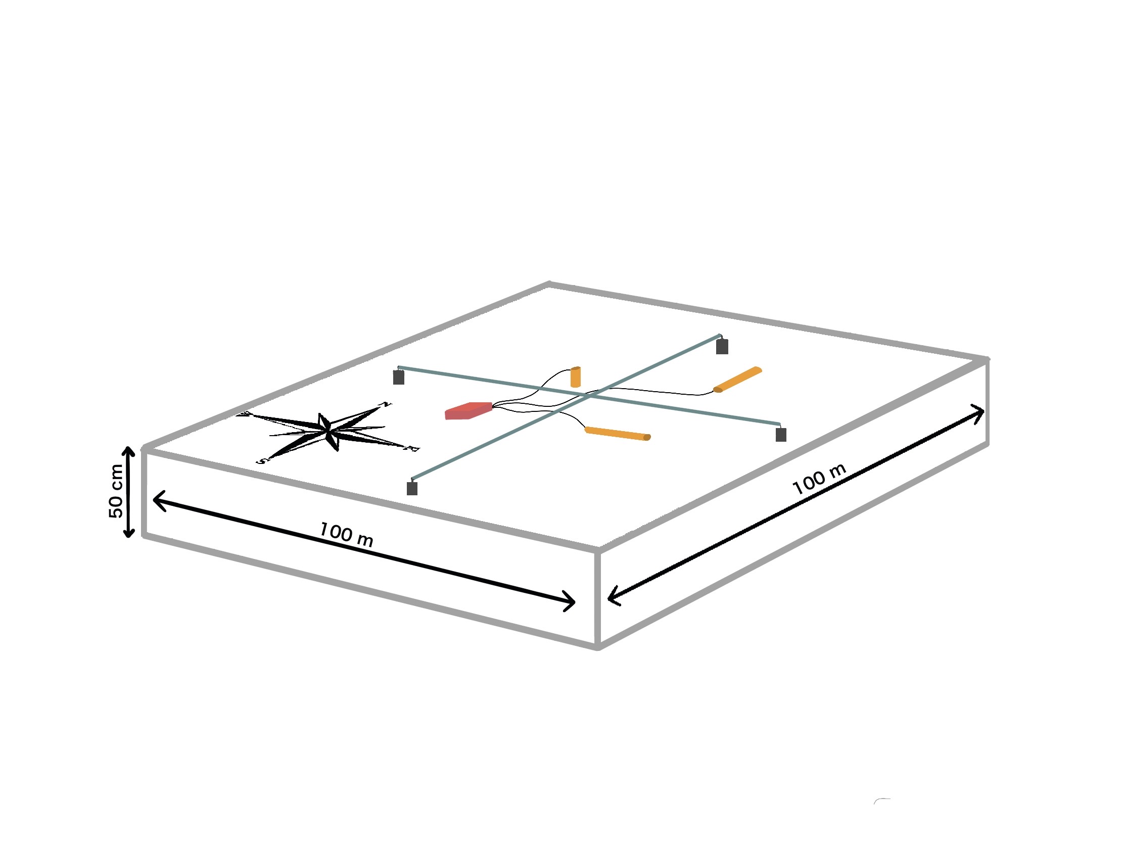
Figure 1 : scheme of a survey site. The orange cylinders represent the tubes containing the magnetometers sensors, each oriented in
a different direction, and buried 50 cm in the ground. The green lines represent the dipole wires for measuring the ambient electric
field.
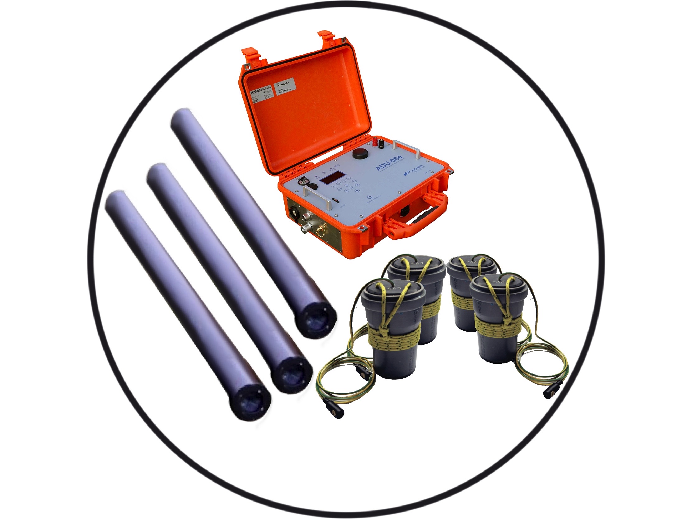
Figure 2: the magnetometers sensors, the tubes in which they are inserted and the acquisition box.